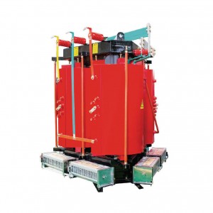
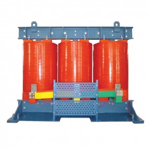
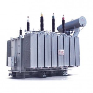
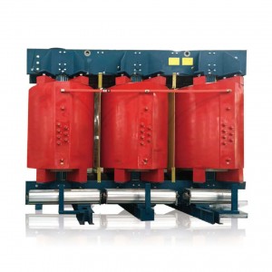
S11~S13 10kV-35 kV Low-loss And Non-exciting Regutation Power Transformer
S11~S22 Series 10kV-35 kV Low-loss And Non-exciting Regulation Power Transformer Product Features
Good economic performance
S11~S22 series product in the S9 series based on average reduced 30% no-load loss than idle current S9 70%-85% will.
Long service life
Transformer tank adopts full seal structure, the tank along with box available bolt connection or welding die, transformer oil not contact with air and prolong the life.
Running high reliability
Tank sealing parts were concerned, increased reliability improvements to ensure and improve technology levelof reliability of sealing.
Field area is small
S11-M, S13-M series transformer tank adopts wave plate radialor, when the oil temperature change corrugated plate heat bilges cold shrink can replace storage cabinet role, corrugated plate appearance tank, cover an area of an area small.
Technical Date Of S11 Series 10kV Low-lors And Non-exciting Regulation Power Transformer
|
Rated capacity(kVA) |
Voltage Combined |
Vector-group |
No-load Loss(w) |
Load loss75℃(w) |
No-load current(%) |
Short-circuit Impendance(%) |
||
|
HV (kV) |
Tapping Ranges |
LV (kV) |
||||||
|
30 |
6 6.3 10 10.5 11 |
±5% ±2x2.5% |
0.4 |
Dyn11 Yyno |
100 |
630/600 |
0.80 |
4.0 |
|
50 |
130 |
910/870 |
0.75 |
|||||
|
63 |
150 |
1090/1040 |
0.75 |
|||||
|
80 |
180 |
1310/1250 |
0.70 |
|||||
|
100 |
200 |
1580/1500 |
0.65 |
|||||
|
125 |
240 |
1890/1800 |
0.65 |
|||||
|
160 |
280 |
2310/2200 |
0.60 |
|||||
|
200 |
340 |
2730/2600 |
0.50 |
|||||
|
250 |
400 |
3200/3050 |
0.50 |
|||||
|
315 |
480 |
3830/3650 |
0.45 |
|||||
|
400 |
570 |
4520/4300 |
0.45 |
|||||
|
500 |
680 |
5410/5150 |
0.40 |
|||||
|
630 |
810 |
6200 |
0.40 |
4.5 |
||||
|
800 |
980 |
7500 |
0.35 |
|||||
|
1000 |
1150 |
10300 |
0.35 |
|||||
|
1250 |
1360 |
12000 |
0.30 |
|||||
|
1600 |
1640 |
145000 |
0.30 |
|||||
Technical Date Of S11 Series 20kV Oil Immersed Power Transformer
|
Rated capacity(kVA) |
Voltage Combined |
Vector-group |
No-load Loss(w) |
Load loss75℃(w) |
No-load current(%) |
Short-circuit Impendance(%) |
||
|
HV (kV) |
Tapping Ranges |
LV (kV) |
||||||
|
30 |
20 |
±5% ±2x2.5% |
0.4 |
Dyn11 |
90 |
660 |
2.1 |
5.5 |
|
50 |
130 |
960 |
2.0 |
|||||
|
63 |
150 |
1145 |
1.9 |
|||||
|
80 |
180 |
1370 |
1.8 |
|||||
|
100 |
200 |
1650 |
1.6 |
|||||
|
125 |
240 |
1980 |
1.5 |
|||||
|
160 |
290 |
2420 |
1.4 |
|||||
|
200 |
330 |
2860 |
1.3 |
|||||
|
250 |
400 |
3350 |
1.2 |
|||||
|
315 |
480 |
4010 |
1.1 |
|||||
|
400 |
570 |
4730 |
1.0 |
|||||
|
500 |
680 |
5660 |
1.0 |
|||||
|
630 |
810 |
6820 |
0.9 |
6.0 |
||||
|
800 |
980 |
8250 |
0.8 |
|||||
|
1000 |
1150 |
11330 |
0.7 |
|||||
|
1250 |
1350 |
13200 |
0.7 |
|||||
|
1600 |
1630 |
15950 |
0.6 |
|||||
|
2000 |
1950 |
19140 |
0.6 |
|||||
|
2500 |
2340 |
22220 |
0.5 |
|||||


