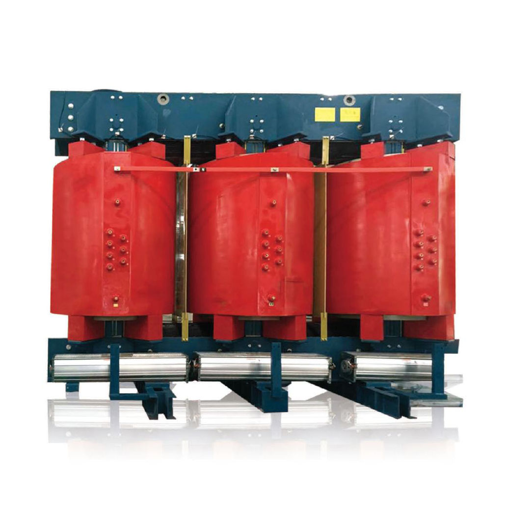
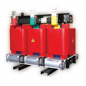
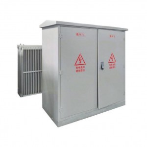
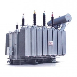
SCB10, SCB11, SCB12, SCB13, SCB14, SCB18 Epoxy-resin Insulation Dry-type Transformer
SCB10、SCB11、SCB12、SCB13、SCB14、SCB18 Series epoxy-resin insulation dry-type transformer Product Features
Security, flame retardant fire prevention, no pollution, can directly mounted in load center.
Maintenance free, easy installation, integrated operation cost is low.
Moistureproof performance is good, can be in 100% humidity, after the normal operation of the action can be put into operation gets.
Dry Low df, local put power, low noise is small, cooling ability, forced air cooling conditions can be rated load operation 150%.
Equipped with perfect temperature protection control system for transformsr, provide a reliable guarantee safe operation.
High reliability, according to the product to have already been put into operation, the operation reliability of products has reached the Inkrnational advanced level.
SCB10、SCB11、SCB12、SCB13、SCB14、SCB18 Series epoxy-resin insulation dry-type transformer Structure characteristics
Box coil: low voltage winding adopts segmental copper foil, along with F grade in the low-pressure foil insulation turms on special around around the system. Foil type coils has solved the low voltage, large currenl coil shorl-circuit stress around the product, Ann circle imbalance, cooling effect is poor, exist around the system spiral Angle, artificially welding quality unstable outstanding problems. At the same time I company winding ends potting with resin, curing forming, moistureproof antifouling. Fuses copper platoon diameter argon arc welding automatic welding.
Temperature control device: transformer USES BWDK series temperature sensor signal thermometer, buried in the low-pressure coil, upper automatic detection and touring show phase of their respective working temperature coil and overtemperature alarm and tripped function.
Technical Date Of SCB 10 Series 20kv Epoxy-Resin Insulation Dry-Type Transformer
|
Rated capacity(kVA) |
Voltage Combined |
Vector-group |
No-load Loss(kw) |
Load loss120℃(kw) |
No-load current(%) |
Short-cicuit Impendance(%) |
||
|
HV (kV) |
Tapping Ranges |
LV (kV) |
||||||
|
50 |
20 22 24 |
±5% ±2x2.5% |
0.4 |
Dyn11 Yyn0 |
380 |
1300 |
2.4 |
6 |
|
100 |
600 |
2100 |
2.2 |
|||||
|
160 |
750 |
2600 |
1.8 |
|||||
|
200 |
820 |
3100 |
1.8 |
|||||
|
250 |
940 |
3600 |
1.6 |
|||||
|
315 |
1080 |
4300 |
1.6 |
|||||
|
400 |
1280 |
5100 |
1.4 |
|||||
|
500 |
1500 |
6100 |
1.4 |
|||||
|
630 |
1700 |
7200 |
1.2 |
|||||
|
800 |
1950 |
8700 |
1.2 |
|||||
|
1000 |
2300 |
10300 |
1.0 |
|||||
|
1250 |
2650 |
12150 |
1.0 |
|||||
|
1600 |
3100 |
14600 |
1.0 |
8 |
||||
|
2000 |
3600 |
17250 |
0.8 |
|||||
|
2500 |
4300 |
20400 |
0.8 |
|||||
|
2000 |
3600 |
18800 |
0.8 |
|||||
|
2500 |
4300 |
22400 |
0.8 |
|||||


